LoRa, LoRa, LoRa!

Summary of Transceivers

Round 1

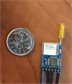
Reyax RYLR896 module (have 3 of them) – contains RYLR890 RF module (which apparently contains Semtech SX1276 RF chip) + STMicro STM32L151C8T6A MCU – has TTL async interface, so used USB to TTL serial to talk to it.  Reliable communications but weird, uses “AT” command set.  I see this as being a replacement for the EOL’d Linx Technologies FHSS radios on the RMM – but the command protocol is different, so I’d have to rework the Microchip PIC18LF4321 MCU code.  To replace the CM, I’d use this module and say the Silicon Labs EFM8UB2 Universal Bee to translate the weird commands to emulate the old Linx FHSS radio.  The EFM8UB2 has built-in USB interface, SPI, 8051 core, and lots more – I used it in the DC Module at ERLPhase, and I like the chip.  I have the dev kit for it.

Ronoth LoStick (have 2 of them) – contains Microchip RN2903 RF chip + USB interface.  I got them to talk to themselves, that was easy.  I’d love to use this to replace the Collector module, but it’s not clear how to get it to talk to the Reyax RYLR896, haven’t been able to make it work.  Its settings are very different than the Reyax RYLR896, so I haven’t been able to make them intercommunicate.  The internal design and internal software do not appear to be open source.

Waveshare SX1262 LoRa HAT for Raspberry Pi (have 1 of them) – contains EByte E22-900T22S RF module (which apparently contains Semtech SX1262 RF chip + not sure which MCU) also has USB interface that I used to talk to my computer directly to the EByte module.  This looks cool, has its own Wiki page describing it, and example code.  I modified a Python program to talk to it, but couldn’t get it to respond.  Tried all the baud rates, put a bunch of debug in there, just not responding… although I seem to see blinky lights saying that the RX & TX are working…

HopeRF RFM95W little LoRa module (have 2) – pretty small – almost small enough to use on a puck – castellated “postage stamp” SMT mount.  Apparently has an Semtech SX1276 RF chip inside – which should make it compatible with the Reyax RYLR896… it needs sync serial (SPI) and I have no easy way to talk to it.

Microchip (formerly Atmel) SAMR34 (have 1 DM320111 SAM034R Xplained PRO dev kit).  This is yet another architecture, contains a 32-bit ARM Cortex M0+ MCU and LoRa Transceiver.  I have not tried it yet.

Round 2

Seeed Systems Dragino LoRa/GPS HAT for Raspberry Pi has a HopeRF RFM95 (ordered 2 on 2020-04-11 – arrives in about 2 wks) (not “W” – not for North America) on it, but I plan to change it to my HopeRF RFM95W so can control directly from my Raspberry Pi through its SPI port.  This appears to be an open design with its own Wiki page, and there’s instructions on how to set it up to do LoRa on the Raspberry Pi, and Github code to do LoRa on the Raspberry Pi.  This LoRa/GPS HAT for Raspberry Pi also appears to be available from Antratrek in the UK.

Adafruit has a RFM95W LoRa Transceiver breakout board that would make it easy to play with the Hope RFM95W, but they are out of stock, Antratrek in the UK appears to have some.  There are similar products from Tindie and another one from Tindie.  Maybe I’ve got enough RFM95W options at present.

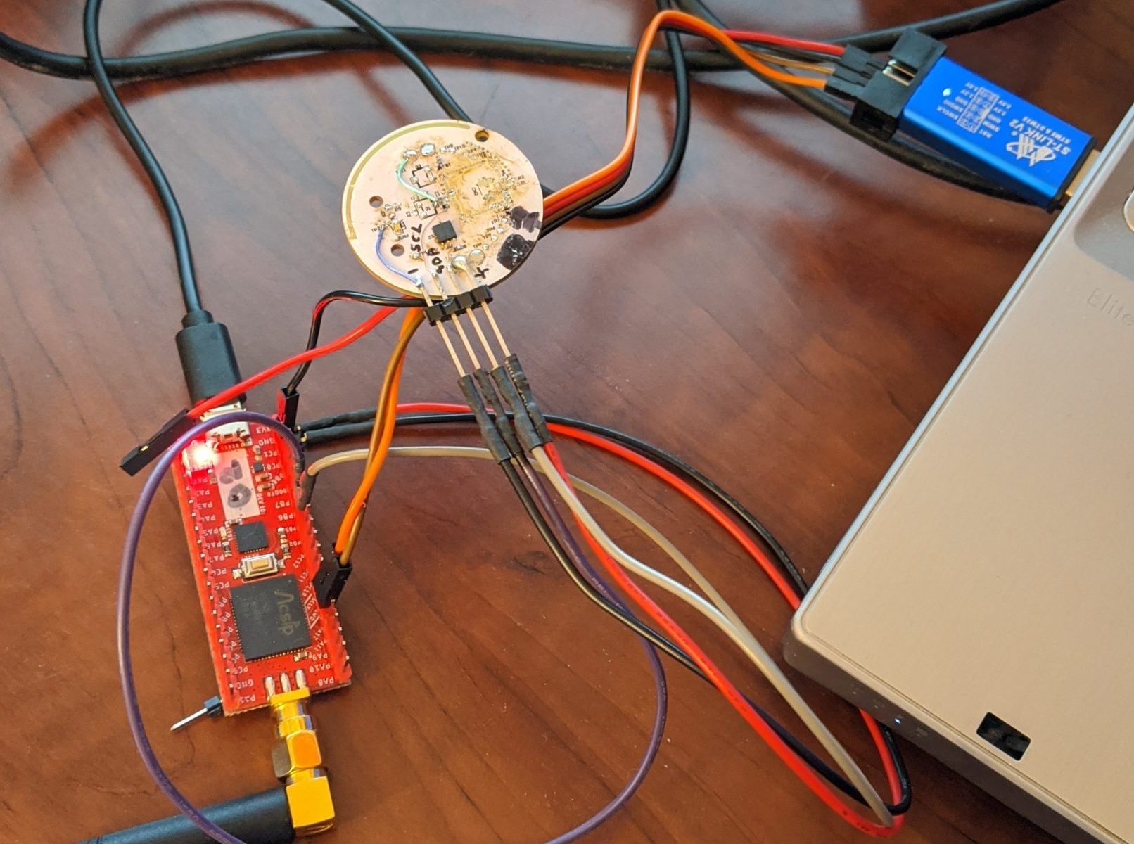
Ronoth  LoDev  ( Ronoth are the folks who made the LoStik).  It’s a bit newer than LoStik, appears to be a different focus.  It uses the AcSip S76S system-on-a-chip (which they call SiP – System in Package).   The S76S contains a Semtech SX1276 RF chip and a STMicro STM32L073x MCU.  It’s sold out at Ronoth, but CrowdSupply says they have some, so I ordered 2 pcs from CrowdSupply on 2020-04-12.

Round 3


I retrieved my personal Raspberry Pi 3 B+ from the office – where I had it placed to facilitate my staff being able to navigate to an important source scanning site from their homes – no longer required because the local IT folks spun up an Ubuntu virtual machine to use instead.  I put the Waveshare SX1262 LoRa HAT for Raspberry Pi onto my Raspberry Pi, and gave it a try.  Well, had to remove the Raspberry Pi from its nice little plastic Adafruit box, because the LoRa HAT interfered with the internal ribs.

Anyway, after some fiddling, I was able to get the first stage of talking to the LoRa HAT to work… but after ser.inWaiting() said there were characters waiting at the port, the subsequent ser.read() call caused an unceremonious abort.  No message, no nothing.  I wasn’t happy with this, but after playing around for a bit, I abandoned my efforts.  Oh, well.

So, overall with the Waveshare SX1262 LoRa HAT for Raspberry Pi , it seems that the mode pins are important and have to be twiddled in order for the board to work.  That’s probably why I couldn’t make it work on USB from my LINUX computer.  That’s a problem for another time, perhaps.

Round 4


Back to the Waveshare SX1262 LoRa HAT for Raspberry Pi .  With manually twiddling the pins, I can talk to the RF module in configuration mode, and got it to respond.  There seems to be a “temporary” configuration and a non-volatile configuration.  Even when I’ve written the parameters I want to non-volatile configuration, then unplug, switch mode bits to talk through the radio, and have the Reyax RYLR896 module chattering away beside it, I get nothing.

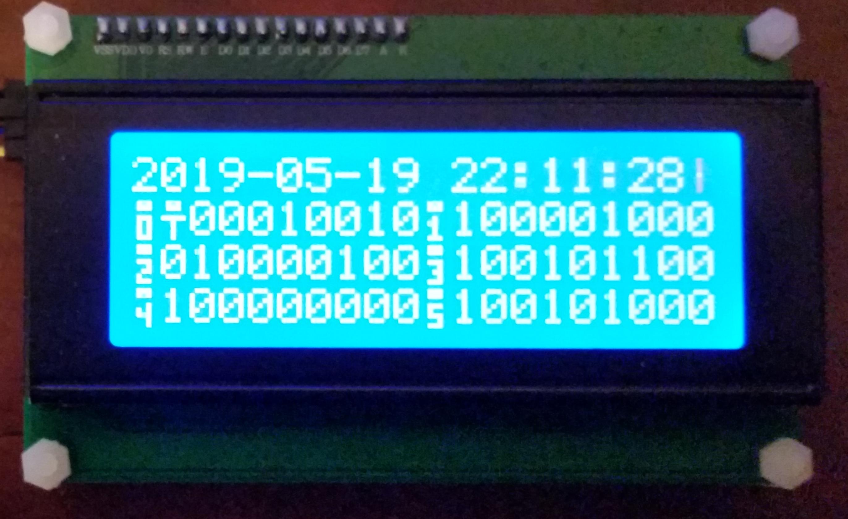
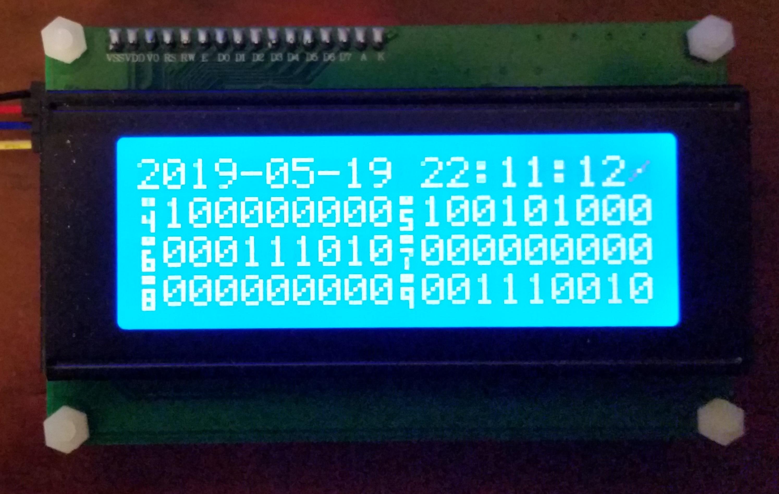
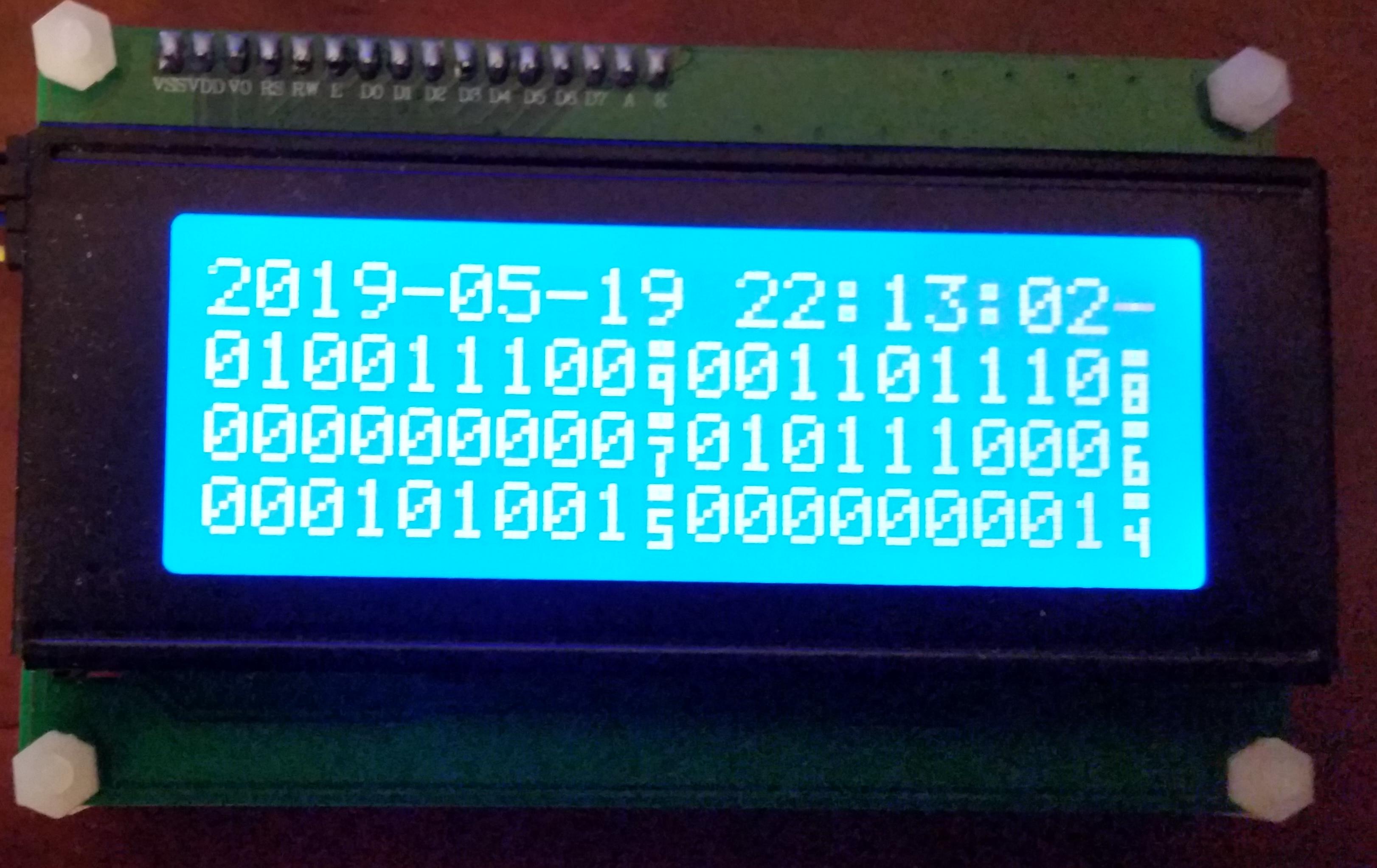
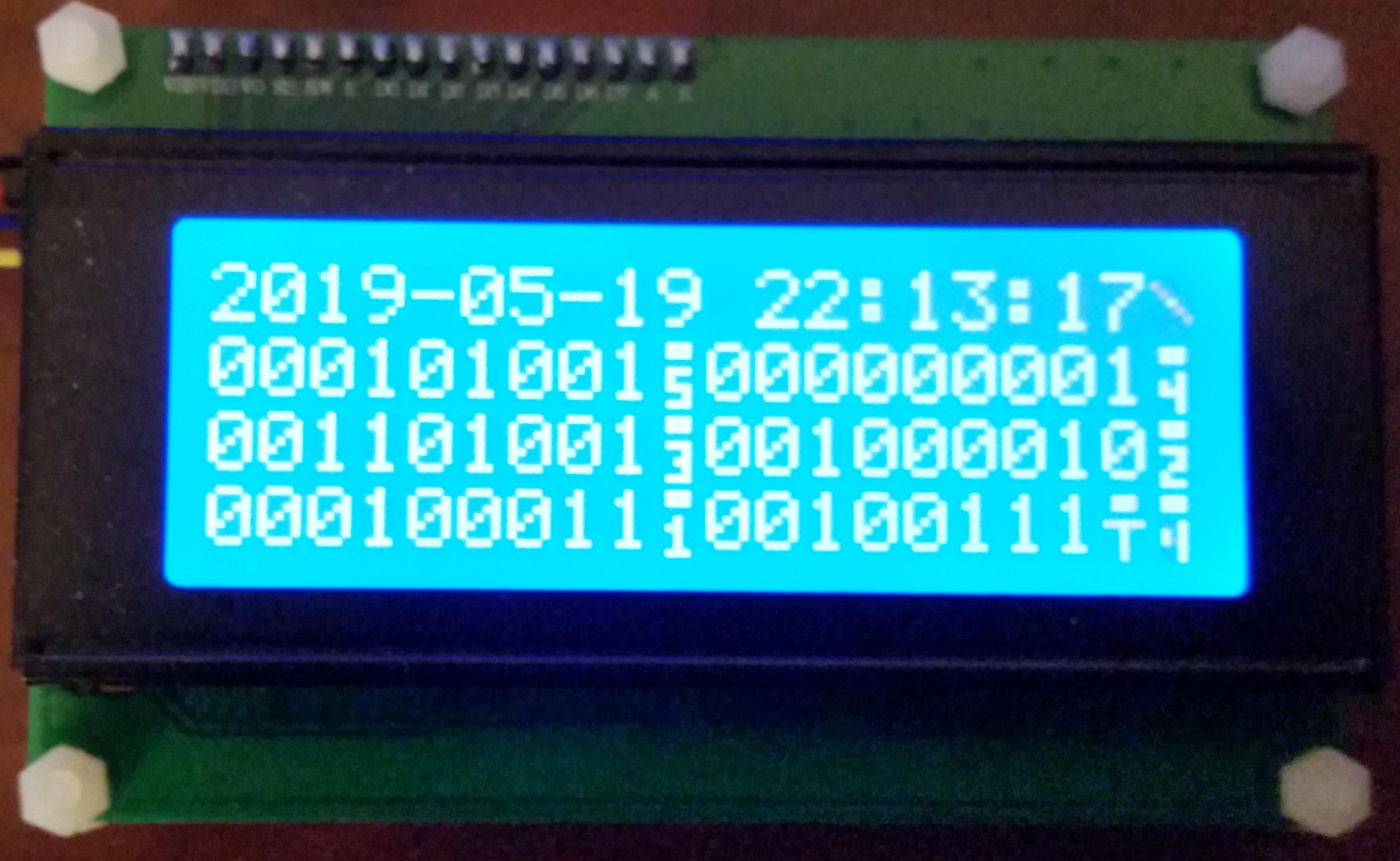
What I have is one Reyax RYLR896 module set as Network ID 6, Node ID 10, alternating transmissions to Node IDs 20 and 30 (yes, in decimal – I checked).  Then I have a second Reyax RYLR896 module set as Network ID 6, Node ID 20, receiving the alternate transmissions.  So, I set the Waveshare SX1262 LoRa HAT for Raspberry Pi set to what I think is the same frequency, and as Network ID 6, Node ID 30 (0x1E)… and receive nothing.

I’m not absolutely sure they are set to the same transmission parameters.  I see no way on the Waveshare LoRa HAT to set Bandwidth, Spreading Factor, Preamble, or Coding Rate.  Hmm, and the frequency is 850.125 MHz + ((0 to 80) x 1 MHz) – so I set it to 915.125 MHz.  Does the 0.125 MHz offset matter?  Argh!

The EByte E22-900T22S RF module , which is the RF module on the Waveshare LoRa HAT, has documentation which is rather sparse.  It documents only 9 registers to set (although it does show all the bit settings) from locations 0x00 through 0x08, and then another 7 bytes of identification at 0x80.  I cycled through the entire space from location 0x00 through then end of the identification.  I found several more non-zero values up to location 0x17.  Perhaps they hold the key to interoperation with the Reyax RYLR896… then again, maybe not.

Read out registers:
0x0000: 00 1E 06 60 00 41 00 00  00 00 00 00 22 14 16 0B
0x0010: 00 00 08 08 C2 03 01 63  00 00 00 00 00 00 00 00

0x0080: 00 22 14 16 0B 00 00


I went to the datasheet for the Semtech SX1262 radio chip that’s inside the Ebyte E22-900T22S RF module, just to see if maybe if I could infer more from that – if the existing E22-900T22S commands were reflected in the SX1262, there might be details of other commands.  Apparently not, the structure is completely different.  It makes sense, because the SX1262 communicates solely by SPI interface… and the E22-900T22S talks by async serial – so there must be a chip inside there to do the interpretation, and perhaps other things in the protocol.  I do seem to recall seeing something about this MCU, but from the Ebyte E22-900T22S documentation, it does not appear to be exposed to the outside world, so working on that could be a severely uphill battle.

Oh well, I’m honing my Python serial skills, and almost ready for the other modules to arrive – Seeed Systems Dragino LoRa/GPS HAT for Raspberry Pi should be here this week – the package is currently in Cincinnati, OH, at the DHL warehouse.  Apparently, the two pieces should arrive on Tuesday.  I hope so – I had to pay duties & fees on it :-(    I will still have to switch the radio module on both pieces – although I might test it at the (wrong for North America) frequency of 868 MHz first.

The Ronoth  LoDev has not shipped from CrowdSupply after a week; I suppose that means that it’s not in stock in their warehouse…  or maybe this COVID-19 trouble has got them waylaid.  That’s unfortunate, because I see the S76S module on the LoDev as the ultimate long-term solution – it has the MCU on-board, I can program it, it has a good example, and can support USB – well heck, maybe the LoDev itself would be the CM replacement.  Anyway, it could work well in both the RMM and the remote in-the-ice measurement “puck”.

Next Steps

The RFM95W Approach


The Seeed Systems Dragino LoRa/GPS HAT for Raspberry Pi has the European frequency LoRa chip on it but the same footprint as the North American frequency HopeRF RFM95W module, which I have here.  I can switch the modules so that the unit is on North American frequencies, then put this onto the Raspberry Pi, load up the Github code to do LoRa and try to talk to the Reyax RYLR896.   I’m not sure if this will lead to a viable solution – it would be more economical to buy Reyax RYLR896 modules and add the EFM8UB2 Universal Bee to translate between the silly “AT” commands and the old Linx Technologies FHSS protocols.  I’d like to replace the STMicro STM32L151 MCU on the RYLR896 board, but the code doesn’t seem complete – looks like it might be a bear to get up and running… might be worth the trouble, if I could maybe just reprogram the STM32L151 MCU to do the whole job and emulate the Linx Technologies FHSS protocols directly (instead of “AT” commands).

The S76S Approach


Assuming that I can get the LoDev from Ronoth to talk, and can program the MCU inside of it, then I could develop a version that would emulate the old Linx Technologies FHSS protocols inside the MCU.  That MCU has USB capability, so it could be a single-chip solution for a revised Collector Module (CM) and still talk to the legacy MS-Windows software using this emulation.  On the other hand, it also has async serial capability, so it could be a single-chip solution to replace the Linx Technologies FHSS modules inside the Remote Measurement Module (RMM) without changing the programming of the Microchip MCU inside it, again using this emulation.  Thirdly, the S76S chip has I2C and SPI capability, and it’s tiny, so with a temperature sensor, it could become the basis of a new “puck” to be buried in the ice as well.

Common Ground between the Approaches


Since both the Reyax RYLR896 and S76S modules have the Semtech SX1276 RF chip inside, it’s also possible that they could both be interoperable with each other… although, based on my recent experience, I won’t hold my breath on that.  Having options is always a good thing!

Beating Up on Some Existing Ones a Bit More


I might work on the Waveshare SX1262 LoRa HAT for Raspberry Pi a bit more.  I seem to recall that I got it to answer to my settings etc., but upon further review of the Python code, maybe I didn’t :-(  I should review again.

A second review of the Ronoth LoStik shows that its settings aren’t so much different than the RYLR896.  Maybe I need to revisit this one.

STMicro ST-LINK Debug Adapters


I’ve also got 2 different ST-LINK/V2 debug adapters – one “official” STMicro one, and one cheap knock-off (because it arrived quicker and was really inexpensive), so if I could figure out how to set up the whole STM32L151 development environment to reprogram the Reyax RYLR896, I could do that.

LoRa in Action?

The LoRa modules came in.  1 x Reyax RYLR896 Module, 1 x Ronoth LoStik USB LoRa stick.  I realized that I didn’t have any TTL level serial devices near at hand to talk to the RYRL896, so then I ordered 2 x Covvy CP2102 USB to 3.3V/5V TTL Serial devices.

There are some Python code examples available for the LoStik on github, so I snagged them and gave them a run.  The easiest one is to toggle the on-board LEDs, and that worked fine, but the transmit/receive didn’t do much of course, because I don’t yet have anything set up to transmit/receive with!  Sigh.

I did set up a Raspberry Pi 3+ to talk to the LoStik though – with WiFi access, VNC desktop, and full Python implementation.

Once the CP2102s arrived, I wired one up with the RYLR896, plugged it in, found out that it enumerated as /dev/ttyUSB0 on my system, and fired up minicom with the default settings of 115200 bps, 8/N/1.  Sure enough, I could get a response from the RYLR896, but it constantly said “+ERR=1” with every character.  I’m pretty sure that it timed out between characters.  Try as I might, I couldn’t get minicom to batch up the characters and only send when I hit .  Well, that and it was confusing on how to get at the end of the line…  let’s see…  stty cooked </dev/ttyUSB0… what else???  Argh.

So I installed and tried puTTY.  It’s in the repos, apparently!  Wow.  Same thing, argh.

Then I tripped over this Youtube video showing use of the RYLR896, and it showed a terminal emulator called CoolTerm, available for LINUX, Mac and MS-Windows.  Sure enough, it’s the real deal, with a GUI, and the right options to allow “Line Mode”, Local Echo, and CR+LF on .  It worked!

The RYLR896 “AT” commands are case sensitive.

Now, to see if I can get the LoStik to talk to the RYLR896…

I’ve ordered a second LoStik and a SX12621 LoRa HAT for the Raspberry Pi.


Modern RF Communications Modules

Filipe and I have been looking into expanding and extending the Eye on the Ice(tm) system for Hans Wuthrich of Ice Consultants International.  The original system was developed around 2008/2009 by my team at Norscan Instruments Ltd., back when we were diversifying our product offering.  I was Product Development Manager with a fantastic group of very talented people working with me.   They did a great job of the design of the Remote Measurement Module (RMM), the Collector Module (CM), and the MS-Windows software that went with it.  It’s a great system!

Alas, RF modules eventually go obsolete, and the ones used in the Eye on the Ice system will likely soon be unavailable.  They might be around for a few years, who knows, but the writing is on the wall – technology changes, RF emissions regulations tighten, and products change.

Last fall, and into the new year, Filipe and I did a proof-of-concept for an in-ice Eye on the Ice sensor which would use Silicon Labs Zen Gecko EFR32ZG14, the Zen Gecko.  Although the system did work, we found that the low-level control of a mostly-asleep sensor was going to be a huge job.  The examples given, and the information provided, just weren’t enough to get us over the challenge.  In addition, the Z-Wave devices appear to “retry themselves to death” if the central station goes away – not a good thing for a low-cost, sealed temperature sensor device.

One thing that looks like an interesting alternative is the LoRa system – long range, low data rate, adaptable for different jurisdictions.  Probably an excellent alternative for transmission of data like Eye on the Ice.

There are modules available to test – look at the Reyax RYLR896 LoRa Module at Amazon, a LoRa Hat for Raspbery Pi at Amazon, a LoRa USB stick at Amazon.  There also seems to be a LoRa book, but it has bad reviews.

The Reyax web site has a few interesting LoRa modules.  Their modules use “AT commands” to set centre frequency, spectral parameters, and data rate.  With that in mind, these modules could almost be a drop-in replacement for the present Linx FHSS modules that Eye on the Ice uses!

The RYLR896 LoRa module from Amazon is documented here – along with specifications for the “AT commands”.  The board-mount module that it’s based on is the RYLR890 which is documented here.

The MicroChip (formerly Atmel) LoRa offerings are also interesting.  There is the R34, a low cost BGA SoC that has a 32 bit ARM plus a multi-band LoRa radio.  It’s available on the cool DM320111, a US$99 reference design / development kit, also available from Amazon for the same price.  One concern is that the documentation talks about the LoRaWAN protocol stack, which we’d want to turn off, so we can just talk simple serial from station to station.

Then I found the Hope RF series of LoRa modules, very interesting, especially the RFM95W.  It looks like it’s just what we need.  It does simpler modulation as well, just by flipping a bit in its configuration.  You would lose all the error correction hyper sensitivity, and built-in spread spectrum, but it would be an easy way to establish simple communication. There seems to be plenty of documentation on the chip, the RF95.  If you Google “HopeRF RF95”, you will find RFM95_96_97_98W.pdf on the SparkFun web page, which gives comprehensive documentation of the chip, its operation, and its registers.  I suspect SparkFun stocks, them, and Digi-Key has them as well.  There appears to be a nice Demonstration Kit, the RFDK_RFM95, but I can’t seem to find a vendor…  GorillaBulderz in Australia lists them but has no inventory, and no indication of when it will be in stock.

OK so maybe it was IRIG madness… (not so much LCD madness)

I’ve been playing, on and off, with IRIG-B decoding – first, modifying NTP source code to continuously dump decoded data from what it reads on the audio input port… then extracting the IRIG-B decoding code to a stand-alone program which would read from the audio input port and output decoded data… then added unmodulated IRIG-B decoding (which was a challenge, due to audio bandpass limitations, but I made it work)…  then putting it to an LCD display, then another, then another with keypad…

Through it all, I struggled to find a practical way of making it useful.  After a discussion with Norbert of ERLPhase, I think maybe we came up with something.

Mobile Device Use?


Rather than expect someone to load up LINUX onto their laptop, drag the laptop to the site where the IRIG-B source is, and use a special cable to connect to the audio input port… why not use the mobile device that everyones seems to carry around with them?

I briefly tried to capture the IRIG-B signal (modulated and unmodulated) into a mobile device, without success :-(    I tried both my Samsung Galaxy S5 (SM-G900T) and my Samsung Galaxy Tab S2.  No luck.  Maybe my physical setup might have been a bit precarious – I found out later that my audio jack connection may have been suspect – but, the result, even when it did seem to get signal, was not good.  A severely attenuated low frequency response (basically gone below about 100 Hz) made it almost impossible to decode the audio captured by either device.

Create a USB OTG Device?


Having used the Silicon LabsUniversal Bee EFM8UB2 processor last year while working at ERLPhase, and after talking to Norbert… why not capture the IRIG-B signal on the USB2’s analog input port, and then funnel it to any customer’s mobile device through the UB2’s well-integrated USB port?  After all, most modern Android devices support USB-on-the-go, where the mobile device can act like a USB host (similar to a computer) or a USB device (similar to a USB flash drive, camera, or MP3 player).

I thought maybe the EFM8 could do simple 8 ksamples/second signal acquisition (the sample rate used by NTP and later read_irig programs), then send packets of data to the mobile device, where it would be saved to a file that would be submitted for post-acquisition analysis.  This way, the burden of processing would be moved from real-time to remote post-acquisition, maximizing the likelihood of successful data capture.

Universal Bee Development Kit


I acquired the SLKSTK2001A Universal Bee EFM8 UB2 Development Kit and played with the examples.

Oscilloscope Example


The SLKSTK has a neat little graphical LCD display and a few buttons on it, and one example supplied was a simple oscilloscope program EFM8UB2_Oscilloscope which could acquire data on an analog input at 24 to 500 ksamples/second.  I created a custom version of this software locked at a sample rate of 8 ksamples/second with favourable amplitude and trigger settings.  I was readily able to see unmodulated IRIG-B waveforms!  Unfortunately, the EFM8 device only does unipolar conversions, and SLKSTK doesn’t have any circuitry to enable bipolar input – so modulated IRIG-B would only show half cycles.

I introduced a crude offset by wiring a 47k bias resistor to the analog input from the 3.3V supply bus.  Together with the 10k-22k-10k divider chain on the input, this gave a reasonable DC offset, so both modulated and unmodulated IRIG-B could be seen.

VCPXpress Echo


A second example supplied was a program to emulate a Silicon Labs CP210x serial port on the USB interface, EFM8UB2_VCPXpress_Echo, which performed a simple reflection echo of characters sent out.

To prove that it was working, and not just a local echo from minicom – ugh sometimes minicom frustrates me – I modified the Echo program to echo every character twice, then follow every character with an arbitrary string “Burp!” and carriage return.  It took a bit of doing, but it worked.

Oscilloscope with added VCPXpress USB Transmission – Failed


Well, I had the 8 kS/S data acquisition in my modified Oscilloscope project, so I mashed it together with the VCPXpress libraries… and got crap.  It seems as thought the whole thing messed up the link process so badly that symbols resolved, but overlapping memory areas caused unpredictable behaviour… and it would not run.  There was just too much gratuitous complexity in the Oscilloscope project.  So, I thought I would work the problem from the other end.

Starting with VCPXpress


I started with EFM8UB2_VCPXpress_Echo, putting out canned strings.  I wrote a simple Python script on my LINUX machine to accept the strings.  That worked.

I added framing and a packet structure to the strings, and decoding into the Python script.  That worked too.

I had thought that I’d send the full 10 bit ADC values, packing them as needed into the serial stream.  However, the nominal line rate is 115 kbaud, or about 11,500 characters per second.  Sending 8 kS/S of 10 bit data would take 10,000 bytes per second.  With 5 bytes of overhead per packet,  and 50 bytes of data per packet, then this 10% overhead would result in 11,000 bytes per second, not enough margin to make me feel comfortable that it would be a robust transfer.

In fact, I decided to add 2 more bytes of overhead per packet – a running binary sample count, to tell if overflow or underflow had occurred – so the overhead is now 14%.

Now, the original NTP code only used 8 bit samples, and seemed to work just fine.  So, why not reduce the data size to 8 bits per sample?  Then 8 kS/S of data would be 8,000 bytes per second, and with 14% overhead, still “only” 9,120 bytes per second.

It turns out that the 115 kbaud line rate is conservative, and really only even supported to make legacy software happy – the USB connection is far faster than this, and will transfer much more data than the stated.  So, in the end, with 8 bits per sample, the link is very solid.

Here’s the packet format:

00 --------- SOH
01 --------- TYPE - Echo of Command (presently fixed)
02 --------- DATLEN - Data Length (binary)
03 -------+
 .        +- DATLEN bytes of binary data
 .        |
DATLEN+2 -+
DATLEN+3 --- CKSUM - sum TYPE to CKSUM (inclusive) is zero
DATLEN+4 --- EM - end marker - end of frame


The binary data that I typically send is 52 bytes total, including 50 bytes of analog data:

00 --------- Acquisition Count High Byte
01 --------- Acquisition Count Low  Byte
02 --------- First Data Sample
 .
 .
DATLEN-1 --- DATLEN-2th Data Sample

Data Acquisition and Transmission


I added data code to make the 8 kS/S ADC acquisition, directly timer driven for jitter reduction, interrupt at the end for buffer stuffing.  The data was reduced from 10 bits to 8 bits at interrupt level.  Two swing buffers were employed, with main line code creating the packet and firing it off to the VCPXpress code for transmission.

Python Processing

Data Reception and Processing


I modified the Python script to receive the analog samples and stuff them into a list, keeping track of whether packets were valid and all samples were present, then writing them to a CSV for processing in a spreadsheet.  I was able to verify that the data was transferred intact and complete, with reasonable fidelity.

I then proceeded to decode the unmodulated IRIG-B signal bits as (0/1/Position Indicator/Invalid), and add them to the CSV file output.  Then, I decoded the signal bits and compose a string of characters to represent each one-second frame of IRIG-B data.  Lastly, if the frame met proper format criteria (PIs in the right places, 1/0s in the right places, not too many bits), I pulled the data out and performed full decoding just as I had done with read_irig in the past.  I also added this to the CSV file output.

I actually created three CSV file outputs:

  • Raw data sample file – with extended columns for bit decode internal data
  • Bit decode sample file – each bit as it was decoded – with extended column for full decode output when successfully performed
  • Full decode file – a bit string for each one-second frame, plus fully decoded data

Threshold Detection


It was difficult to consistently get good thresholds for decoding, so I added rescaling.  The maximum and minimum values of signal in the file are calculated.  An offset is subtracted to centre the signal around zero, then a gain is multiplied to make the signal approximately -3 dB of full scale, or about +/-25,000 counts.

Modulated IRIG-B Processing


It was difficult to decide how to work with modulated IRIG-B.  The original NTP code did a kind of phase-locked loop decode on the signal, so it could recover the bit stream, but also the precise zero cross time, so the local clock could be time sync’d to the IRIG-B signal.  I didn’t want to do this.  The code is hard to understand, we don’t need time sync for post processing, and I’d rather not incorporate someone else’s code if I don’t have to.

Instead, I went back to the way that Filipe and I designed modulated IRIG-B processing so many years ago: watching for positive side pulses due to the sinusoid going above zero (Polarity), and also for “high” level amplitude by positive side pulses due to the sinusoid going above a threshold (Peaks).  Polarity without Peak means low level cycle, Polarity with Peak means high level cycle.

One problem was an unknown baseline.  As mentioned, an arbitrary offset had been applied.  The maximum and minimum values of signal in the file are calculated.  Zero cross was assumed to be at the halfway point – the median – the average of maximum and minimum – this gives Polarity.

The amplitude of a low level cycle is defined as 1/3 the amplitude of a high level cycle.  The threshold would be halfway between these two levels, or 2/3 the amplitude of a high level cycle, or 5/6 of the way to maximum level – minimum + (5/6 x (maximum – minimum))

Now, I tracked how many high level cycles in a row happened before low level cycles resumed.  This would determine whether a bit was a 0/1/Position Indicator.

Tarball and Steganography


I added a feature to roll the three CSV files up into a GZIPped tarball.  Because the files are ASCII, they compress well.  Then the original CSV files are deleted.  A tarball is easier to transfer for post processing.

A tarball might not pass E-mail inspection, so I added a steganography library to encode the tarball into an arbitrary JPEG image.  The JPEG image would likely get through the E-mail system more easily.  However, this processing took a very long time (over 10 minutes) and created a huge image file (original 100k, over 5 Meg afterwards), so this was abandoned.

Improvements

Automatic Gain Control


By putting the EFM8 MCU’s VREF on an RC-integrated PWM output, and using the same signal as a DC bias offset on the analog input, I could change the bias and the ADC span under program control.

I added code to the EFM8 to track the maximum and minimum ADC input levels (single ended) and calculate whether the system gain should be increased or decreased to make the span approximately 128 counts, or about half scale.  Margin is maintained, but gain is maximized.  The system is designed to track within a second or two of amplitude change.

Building it Onto a Beadboard


The analog circuitry was put onto a breadboard and wired to the EFM8 MCU on the development kit.

Silicon Labs SLKSTK2001A EFM8 UB2 Universal Bee Demonstration Board with Simple Analog Front End
Silicon Labs SLKSTK2001A EFM8 UB2 Universal Bee Development Kit with Simple Analog Front End

Next Up


Next, to connect this to a mobile device, invoke a serial port driver, and capture the data there for post processing analysis.  That’s easier said than done!


Please Send with the Other Foot…

My dad passed away a couple of years ago, in February 2017.  We were estranged.  It’s a sad tale, I suspect too often repeated in many families.  Fights, misunderstandings, dumb egos, idiotic attitudes towards children and parents, and other assorted foolishness.

Dad had moved to the Philippines around 2013, but I didn’t know that until some time later when a woman tried to contact me, claiming to be his new (but already estranged) wife there.  I declined to get involved in their child custody fight – I know nothing of the situation, knew nothing of his whereabouts or his activities, and only had her word on it all.

I am kind of sorry that I didn’t at least try to track him down, not to assist her, but to at least make contact, while he was still alive.  Sigh.

Apparently, a heart attack felled him, at the age of 77.  That’s not all that surprising, as he smoked on and off throughout his life – most of the time I knew him, he was puffing away.  One of the reasons why I can say that I will never smoke.  Haven’t had a single one yet, and don’t intend to start – and I hate the smell.  Well, enough about that :-)

Running off to join… the Railroad?


But, 60-some-odd years prior, he was a strapping young lad of, oh, probably 17 years of age (1957?), when he quit school and went to work for the CNR station in his hometown of Makinak, Manitoba.  He signed on as a telegrapher, then moving all around Manitoba and Northwest Ontario, working out of one horse towns, sidings, and places-in-the-middle-of-nowhere.  I know that he worked a time in Churchill, around the time I was born – because my mom says that they would do “check-in” calls once a week – he would make a person-to-person call asking for himself – which my mom would of course decline, saving the toll charges, but knowing that he was still alive.  Long distance charges were pretty steep in those days, and money was tight for my parents.

My dad left the railroad sometime in 1963 or 1964, apparently when the switch from telegraphy to teletype was on.  The railroad left a lasting impression on him, though – he had a lifelong love of trains, talked fondly of his time with the railroad, and cherished his telegraphic memories, so to speak. He also used to say that he worked there long enough to get coal cinders in his hair.

Ernie Letain, friend from Laurier, the next stop southeast on the CNR line from Makinak, started with the CNR as a telegrapher at about the same time, but stayed on and became a rail traffic controller, retiring from the CNR many years later after a long career.

When my dad first started, he was shunted around at the whim of the company, working many small places, as mentioned.  As he got more seniority, he could stay closer to home.  He never did build up much seniority, but he did manage to get work from time to time in “WI Office“, which was the CNR telegraphy office in Union Station on Main Street in downtown Winnipeg.

Experienced Professionals vs the Unskilled


My dad told me that often young men from remote places would learn to use the telegraph, and get work with one of the railways, as a ticket out of the sticks, as they would call such way-off places.  Their telegraphy skills would be poor (perhaps like his when he first started out?  Hmmm), so sometimes an urban operator in WI office would ask the remote unskilled operator to please send with the other foot, obviously an insult, since operators always sent with their working hand.

The Vibroplex “Bug” as Telegraph Key of Choice


The Vibroplex “bug” was the high-speed telegraph key that most professional telegraphers used to send code.   When you pressed the paddle one way, it closed a solid contact to send “dashes”, but when you pushed the paddle the other way, a weight and a spring caused a second, smaller contact to bounce rhythmically to send “dots”.  The weight and spring can be adjusted to change the speed of the “dots”.

Dad was a southpaw, a left-hander, so he a rather special version of the Vibroplex “bug”, the relatively rare left-handed bug.  I still have that key, somewhere, in its original box.  It’s dusty, but it still works well.

A Vibroplex left handed Bug

WI Office Telegraph Traffic


My dad told stories a row of operators working in WI Office, with the telegraph sounder on a swing arm moved up close to your ear, so you could hear your own signal over the din of the all the others.  You would listen to the Morse code and type on an old manual Underwood wide carriage typewriter.  I had one of those typewriters for many years.  Oh, but the code used was American / Railroad Morse, not International Morse.

Often the traffic received was mundane in nature – freight car contents and their movements, inventories, and manifests.  Sometimes commercial traffic was exchanged – so called “sending a telegram”, but mostly it consisted of information of interest to the railroad.

When doing manifests and forms, the old Underwood would be set up with “hard” tab stops set for the locations of the form fields.  I’m sure the old typewriter would be very noisy too, with a “clack-clack-bang, clack-clack-bang, ding-return!”

When shorter forms or messages were completed, they were clipped into a rail above the operator’s station, and whipped down the line to where someone else picked them up and distributed them where they needed to go.  Meanwhile, the operator would have already loaded up a new page into their typewriter, probably already partway into copying the rest of the message.

In fact, often operators would not even be thinking as they typed.  It became automatic.  They typed what they heard.

A Lion Runs Away to Join the Railroad Too?


Now, I don’t know if it was my dad or someone else who had this happen to them, but my dad often told the story of an operator, late at night, who was taking a mundane message.  He typed it up, pulled it out of the typewriter, clipped it into the rail, but just as he was about to sling it down the line, he saw the message he had just typed.  It said:

FOUND A LION UNDER STATION IN POOR CONDITION.


Wow, that was interesting!  Where the Hell did the lion come from?

Dad said that it happened due to an anomaly in Railroad Morse code.  Railroad Morse had dots, normal dashes, long dashes, inter-dot/dash spaces, inter-character spaces and inter-word spaces, with supposedly fixed ratios between the lengths of each.  A poor operator could change a “T” to a “

-L”. So what happened is someone was sending with the wrong foot, and was trying to say:
FOUNDATION UNDER STATION IN POOR CONDITION.

A simple status report, when messed up, caused some mirth in WI Office!

Text Graphs with GNUPlot!

I stumbled across this article a few weeks ago, and kept it open in my browser until I could come up with something (semi-) useful to do with it: Plotting data in the terminal with gnuplot

I had done some work last year at ERLPhase to analyze some data, including doing FFTs, etc.  I played around and did a comparison between JPEG graphics and text graphs.  Check it out!

FFT Graph
JPEG FFT using Graphics
TXT FFT using Text
TXT FFT using Text

Click here to see the text FFT in alone in a page or new tab or new window, depending on your browser settings.

The secret to doing a text plot is in the two statements:

set terminal dumb 250 60
plot FftFileName using 2:5 with linespoints


Where the output is 250 characters wide x 60 lines high, and the input data is in the file FftFileName.

I don’t know why, but I find that just… fascinating…   wow!

The LCD Madness Continues

I purchased a Crystalfontz CFA635-YYK-KU 4 line LCD display with integrated USB interface, 4 bicolour LEDs and 6 button keypad, then proceeded to modify the read_irig program to talk to it.

CFA635 Display Showing IRIG-B
Integrated Display with LEDs and Keypad showing IRIG-B

I’ve modified the keyboard interface a bit as well.  Keys now supported:

a - Change backlight intensity (CFA635 only)
d / keypad "DOWN" - Change display format: DECODED, RAW, TITLED
h / keypad "CHECKMARK" - Hold/unhold display
u / keypad "UP" - Reverse RAW or TITLED display order MSbit LSbit
r / keypad "RIGHT" - Shift display data right
l / keypad "LEFT" - Shift display data left
v - Diagnostic dump of display data to terminal
f - Change format of terminal displayed data: RAW+DECODED, DECODED only, RAW only
q / keypad "X CANCEL" twice consecutively - Exit program


I’ve also made the top LED blink green bright and dim, each time it gets a time update, solid red when IRIG input fails and a timeout is declared, and blink orange bright and dim slowly, when display is in hold mode. View a one minute video of it in action, at this link.

Messaging on Computer

Of course, using Facebook Messenger on the computer is just as easy as on your phone…  or is your phone just as easy as computer?  No matter, it’s easy.  For other messengers, you have to get more creative.

WhatsApp


This one isn’t too difficult.  Go to the WhatsApp web site, then try to log in.  It will give you a QR code.  Go to your cell phone, get onto WhatsApp, go to the upper right menu, choose “WhatsApp Web” and point it to the QR code…  Boom!  You have your WhatsApp on your computer and on your phone.

You can’t have WhatsApp web on two computers at once.  If you sign on at work (say), then your home computer is logged out.  Not too bad though, since it’s easy to sign back in again.

This only works when the phone is on-line and has data through WiFi or its own data connection.

Google HangOuts


This is even easier.  If you are logged onto your Google account in your browser, just go to the Hangouts page, and there it is.  You can be logged in on as many computers as you want for this.

Hangouts works whether or not the phone is on, or connected.

SMS (Text Messaging)


There are two approaches here.  Both requires the phone to be on-line and have data (WiFi or its own data) and SMS access.

Google Messages


If you are on Android or otherwise have access to the Google Messages application on your phone, make that your SMS program.  Then you can go to the Google Messages web page and see all the conversations.   The nice thing with Google Messages is that, when you read a message on your computer, it’s marked as read on your phone, so the notification goes away.

PushBullet


This is really cool, and was my go-to solution before I had Google Messages.  Put the PushBullet application on your phone, then go to the PushBullet web page and sign in on both.  You can send and receive your phone’s text messages.

There are two drawbacks to PushBullet.  One is that it costs money to sign up and keep it running (sorry, I forget how much).  The other is that, reading a text message on PushBullet does not mark it as read on your phone, so the notification stays up until you do read it on your phone (or at least cancel the notification).

Kik Messenger


I think here, you are out of luck.  For security reasons, you don’t want to use other company’s programs to dig into the Kik Messenger messages.

Telecom Madness!

I find it cool that I still have the same telephone number that I had in high school.  Yes, if you knew what my phone number was in high school, you can still reach me there now.

Once upon a Land Line


My family moved to Headingley, just west of Winnipeg, in October 1971.  At that time, Headingley was an independent rural municipality, separate from the city of Winnipeg.  We got a rural telephone number (204)-864-xxxx, typical of St. Francois Xavier and Lido Plage, to the west and north, further out of town.  This meant that calling into Winnipeg was long distance, even though it was only about 9 km (5.5 miles) away!  Very annoying.

There was quite a fuss going on in Headingley at the time.  Manitoba Telephone System (MTS), the government owned monopoly on phone service, claimed that if we wanted to have local calls to Winnipeg, then we had to be part of the city.  That was crap.  Communities to the northeast of the city, like Lockport, had local calling to the city, and were not part of the city.  The city of Winnipeg was actually several independent cities at that time, each with its own council and mayor/reeve.

Nonetheless, around 1972 the province of Manitoba amalgamated all the independent cities in an effort called “Unicity”, and in so doing, subsumed Headingley into the City of Winnipeg.  Now, I think that the Unicity concept was a good thing, especially in the area of control of development – although on the other hand, Winnipeg hasn’t done a very good job of development control…  more on that, another time.

So, around 1972, my family got a new Winnipeg phone number, (204)-xxx-1334.   All of my friends knew this number, of course.  And I knew all my friends’ numbers.  It was what we did in those days!

Dean gets his Own Phone – in His Basement Lab


Around 1980 or so, while living at home, I was frustrated by not being able to use the phone when I wanted to, and I had decent income, so I got my own phone installed into my lab in the basement, (204)-xxx-5620.  I was so thrilled!  When I tried to call my best friend Dave, his number was disconnected… oh no!  It turns out that when I was at Polo Park getting my number assigned, Dave’s mom was at another MTS store getting a new number as well, and she got the one just before mine, (204)-xxx-5619.  My personal number is long gone now, but she still has hers, and that’s how I remember it – one less than mine, ha ha ha.

Grabs Control of Old Family Telephone Number


Later, when Dayna and I bought the house and moved out to Headingley with Eric, I called MTS and told them that they had my first initial wrong (my mom’s initial is “M”), so effectively transferred the phone to me, heh heh.  Later, we “ported” the number to Shaw, our cable TV and Internet provider.

When I moved away in 2011/2012, Dayna let the phone lapse.  I called Shaw to get my own phone, they told me it had lapsed, so I picked it up again.

Moving to VoIP… and to Arizona!


In 2013, when I moved to Phoenix, I ported it to VoIP provider Les.net.  I had a Grandstream HandyTone 286 adapter, with a 4-phone Uniden cordless telephone system.  It was very nice in Phoenix, as I could have several phones about the house.

Way cool, I had my long time Manitoba telephone number, and it rang in Phoenix.  Caused pollsters and telephone solicitors no end of confusion, hehehe.

Adding Numbers


While I was in Phoenix, I actually signed up for a couple of other Les.net numbers, including a conference call number in Winnipeg, conference call number in Phoenix, a toll-free (800) number, just going crazy :-)

Toll Free Line


The toll free number was to encourage my mom, my son and my brother to call more often, if they had no long distance.

Conference Call


I used the conference call number for governing board teleconference meetings, when I was chair of SAE Arizona & Nevada Section.  It was a bit expensive, as it cost me 1.5 cents per minute per caller…   and, as I seem to recall, it cost me big one time that someone didn’t hang up before I did!

Features


All the telephone numbers rang to the same phone.  It worked well.  An additional feature was an embedded answering machine – a message left on any number would be converted to a WAV file and E-mailed to me.  I could get them anywhere, how convenient.

And the cost was low, low low!  It’s about $3 a month for an account, which includes an automatically assigned Winnipeg number, then about $3.50 a month to maintain the 1334 number that I ported from Shaw.  Calls were about 1.5 cents a minute (one way more expensive than the other, don’t recall which), so it was really difficult to get up to $10 a month.  Nice!

Now, the sound on that system was not great.  The big challenge that I found was that there appeared to be a significant transit delay for the data.  It’s amazing how very small delays, say 100 mSec, can be extremely frustrating.   You think someone else is stomping on you during talking, but it turns out that it’s because of the small delay.  You have to keep that in mind.

Mom’s “Long Distance Phone”


It worked well enough that I got my mom a Grandstream HandyTone 486 and a 2-phone cordless telephone system, intended only for making calls.  She saved a lot of money using it to make all her long distance calls.

Moving back to the ‘Peg


When I moved back to Winnipeg, I ported my Phoenix cell phone (480)-xxx-5952 into Les.net as well, so I could continue to receive calls and exchange texts with folks who had that number.

Porting to VoIP.ms and Getting a VoIP Desk Phone


One day, I found out about another VoIP provider, VoIP.ms.  I started an account there, just to see how well it worked.  They had better sound quality, and more services, so I transferred my (204)-xxx-1334 and (480)-xxx-5952 to Voip.ms and got a Grandstream GXP1620 2-line VoIP desk phone.  I love it!   The sound is awesome, practically perfect, way better than my cell phone.  I have one line on each number.  Even better, the (204) number costs $1.70 a month, and the (480) number costs $0.85 a month.  I’m paying about 1/2 cent per minute on the (204) number and about 1 cent per minute on the (480) number.

Headset Highly Recommended


When I started applying for jobs all over the place, and having to do so many telephone interviews, I got a DailyHeadset model 4332802404 (ASIN B076KP2SX4) on Amazon (where else :-) ) which plugged right into the GXP1620 and worked flawlessly.  It is fantastic.

SMS Almost as well as a Real Cell Phone!


VoIP.ms actually has an Android application that can text (SMS) through an SMS-enabled account, and my former Phoenix cell phone number (480)-xxx-5952 was such an account, so I can text message anyone in the USA almost as easily as before.  The only thing is that it doesn’t support MMS (pictures, songs, and videos), so, don’t even try.  On the other hand, you can do SMS from VoIP.ms’s web-based portal, so you can SMS from your computer.

They also have the “VoIP.ms SMS” Android application that can use your mobile phone’s data plan to do SMS almost as well as native SMS.  Follow the directions on the VoIP.ms website, you have to set up a “callback”.

The Android application can host SMS for multiple telephone numbers at the same time, allowing you to select between them.

A recent update: it appears that they’ve made SMS available on my original land-line phone as well, so perhaps they’ve lifted the requirement that it was originally a cell phone, to make SMS texting work.

Send and Receive FAXes Too!


VoIP.ms also has FAX numbers you can rent for $2 a month.  That lets you send and receive FAXes using E-mail to/from your computer!  It works great.  I’ve used it only a few times, but it’s a neat toy nonetheless.

Caller ID Foibles


The one challenge that I’ve had using VoIP.ms is the caller ID information on outgoing calls.

I don’t know if it’s my VoIP desk phone or the VoIP.ms system, but it sometimes gives the Arizona number for calls made from line 1 (the Manitoba line) and the Manitoba number for calls made from line 2 (the Arizona line).

Eric also reported that his phone claimed I was calling from Egypt (country code +20), so his phone was misinterpreting the caller ID information.  The start of the “204” Manitoba area code was getting interpreted as the country code.  Contrary to what VoIP.ms tells you, when it asks you to give the 10 digit caller ID number, give them 11 digits, prepending the “1”, and that fixed the problem.

Incoming Calls: the One Challenge


For some reason, incoming calls have been a challenge.  The VoIP server must be able to route back to your VoIP phone, in order to ring it and set up the connection.  Years ago, this seemed easy, and it all worked.  Of course, I didn’t make any notes about how to set it up (argh).  But recently, I found out that neither of my numbers would ring through to my desk phone.  Curses.

My solution was to forward a bunch of ports through my firewall to my VoIP phone.  UDP ports 5060 (1st line), 5062 (2nd line), and 10000-10200, to be precise.  Then I had to deal with my dynamic IP resolution.  Well, I have a subscription to dyndns.org, so I can readily resolve (say) something.dyndns.org (or whatever, they have lots of options for TLDs) to my local firewall’s outside address.  The challenge is getting the dyndns.org  (oops, now that it’s owned by Oracle, they call it dyn.com) server updated.  In the old days, I used an old WRT-54G firewall/router flashed with DD-WRT.  That worked well back in the day, but I’ve abandoned it recently because the WRT-54G got a bit sluggish and lacked features (like 5 GHz band support).  If you go that route, be careful – there are a lot of WRT-54G variants, and not all of them can be flashed to DD-WRT… and some that can, are restricted in functionality once flashed.

Anyway, without my handy DD-WRT router, I set up a Raspberry Pi that runs inside my network, with ddclient connected to dyndns (see directions), which keeps the IP address on dyndns pointed to my firewall/router.


IRIG2LCD()

Decoded Time Display

Well, I did it – what I’ve been trying to accomplish for some time now.  I have a “live” decode of IRIG-B to my little 5×7-character-based LCD display.

Pulling Threads


I created two new threads in my read_irig program.

One thread reads the keyboard, looking for single character commands:

  • q: quit read_irig
  • d: show decoded data
  • r: show raw data 3 lines at a time (60 bits at a time), and if raw data already showing, reverse the bit sequence
  • t: show raw data 1 line at a time (20 bits at a time) with header, and if already showing, reverse the bit sequence
  • u/l: move between windows of present format up/down (e.g. show next or previous 20 bits of raw data)
  • h: freeze the display at the present time


The second thread takes a full structure of present time data and displays it on the screen, in accordance with the present format and situation.

Displayed Output

Decoded Display


Decoded Time Display, showing decoded date, day of year, time of day (HH:MM:SS and straight binary seconds in hex)

Decoded Data Second Page, showing format, gain and amplitude of signal

Raw Display


Raw Data, showing chips 0 to 59

Raw Data Second Page, showing chips 40 to 99

Reversed Raw Display


Reversed raw display is convenient because the bits are arranged from most significant (MSB) to least significant (LSB) from left to right, which is convenient for most people to read.

Reversed Raw Data, showing chips 99 to 40
Reversed Raw Data Second Page, showing chips 59 to 0

Timeout/Searching for Signal Display


Timeout Indication, showing blanked out data, presently searched-for signal type, gain and amplitude of signal

What’s Next?


I was thinking that I might introduce a third display mode, that of raw data with headers, more like the console output of read_irig:

#
#--------------------------------------------------------------------------------------------------||------------------------------------------------------------|
#           Normal Unmodulated IRIG-B Raw  (noninv audio)  (Gain  93 giving  +1.0 dB)              ||   Normal Unmodulated IRIG-B (noninv, gain  93 ->  +1.0 dB) |
# StrtBinSecs (SBS) |    Control Bits   |   Year  |    Day of Year    |  Hours  | Minutes |Seconds ||Day|   Date and Time    |SBS hex|Leap| DST |Offset|Qual|Par |
# ........ .........|......... .........|.... ....|       .. .... ....|  .. ....| ... ....|........||...|.... .. .. .. .. .. | . ....|....|.....|......|  ..|....|
#                   |                   |         |                   |         |         |        ||   |                    |       |    |     |      |    |    |
.001010101.010111101.000100000.010111000.000101001.000000001.010000000.000100010.000001000.01001001. 140 2019-05-20 12:08:29   0_AABD !lsp  DST  UTC-05   00 1 ok 
.001010101.010111110.000000000.010111000.000101001.000000001.010000000.000100010.000001000.01100000. 140 2019-05-20 12:08:30   0_AABE !lsp  DST  UTC-05   00 0 ok

And Then, and Then!?!


You think that would be enough for me?  Well, apparently not!  read_irig takes very little computing power, so it could easily run on a smaller processor…  say, an ARM… on a Raspberry Pi, or a Beagleboard – then it could be made portable.  I have two Beagleboard Blacks and like them.  The problem here is that none of these boards have easy audio input ports, like my laptop.  Some do have ADC inputs, but they need to be protected, amplified, provided with a jack, etc.  Hmm, have to think about this.

Almost every device these days has an I2C port, so there shouldn’t be much trouble there.